Why Lidar is more accurate than CAD contours

There are a few methods to create toposurfaces in Revit. There has been a long debate on the best approach regarding accuracy and convenience. In this article, we shall compare two processes: using contour lines from a CAD file and using Lidar point clouds.
How do contours and Lidar datasets compare in terms of terrain representation?
Contours are a great drawing system to represent terrain and started being used about four centuries ago. It must have been quite interesting to be around when it was introduced. Such a simple way of placing lines with the same altitude on a drawing, contours provide an incredibly intuitive and practical way of presenting a landscape.
Lidar datasets are today the most advanced representation of the Earth's surface. The primary data behind it is a digital system of three-dimensional georeferenced cartesian points. Additional metadata such as RGB color and classification (ground, water, road, building, etc.) also forms part of the LAS binary standard. Such point clouds' extraordinary precision and density can create nearly continuous surfaces that can be visualized, sorted, and analyzed in many ways. We have dedicated a full article that explains the technology, features, and benefits of Lidar for the AEC industry here.
If we focus on the necessary information to generate terrain inside Revit, one can say that contours have an unlimited number of known points along the contours. A Lidar cloud, however, has a limited number of points, but they are in equal distribution along the entire area. So let's evaluate the next point.
How dense is the terrain data using contours versus Lidar surveys?
Contours register the line of pre-determined differences of levels. For instance, the outlines are traditionally at 1-meter intervals in Europe for site surveys. However, the micro variations of the terrain between the contours is not represented in this system. Depending on the inclination of a site, one may have more or fewer points in a contour drawing.
Using Lidar, the situation is quite different; the point density is only depending on the specification and quality of the survey. One can have up to 8 points per square meter on an airborne survey and even more density with a land scan. One can conclude that Lidar is a much more sensitive method that registers the terrain with much more detail. Lets have a look at two images representing a 100x100 meter zone in a Revit terrain created with contours and Lidar using the topography app for Revit.
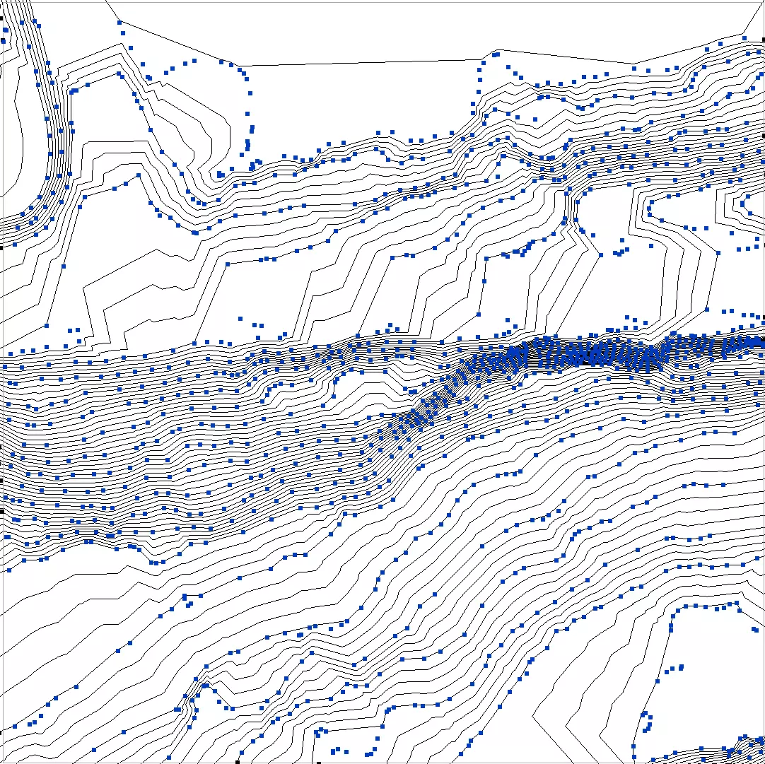
100x100mm area created with contours
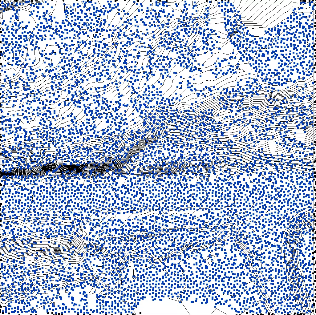
100x100m area created with Lidar.
For the same area, that is one hundred meter square, the Lidar generated terrain has a uniform distribution and 5 times more points that the area generated with contours.
What are the actual differences in accuracy in the resulting Revit toposurfaces?
To compare both terrains, we have used the same area generated with contours and Lidar points and set up the spacing between the Revit contours to 0.25m.
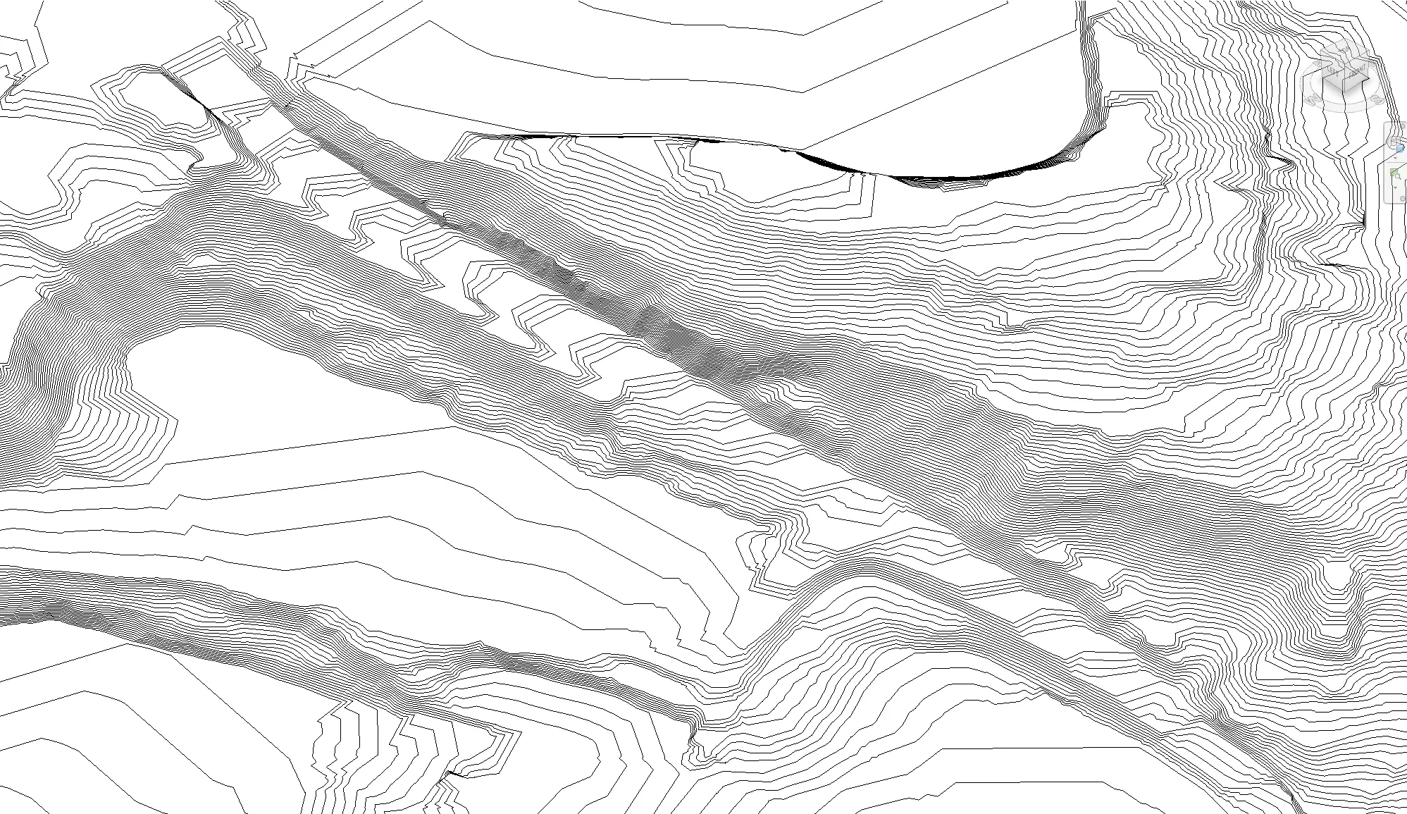
Revit terrain with 1m contours
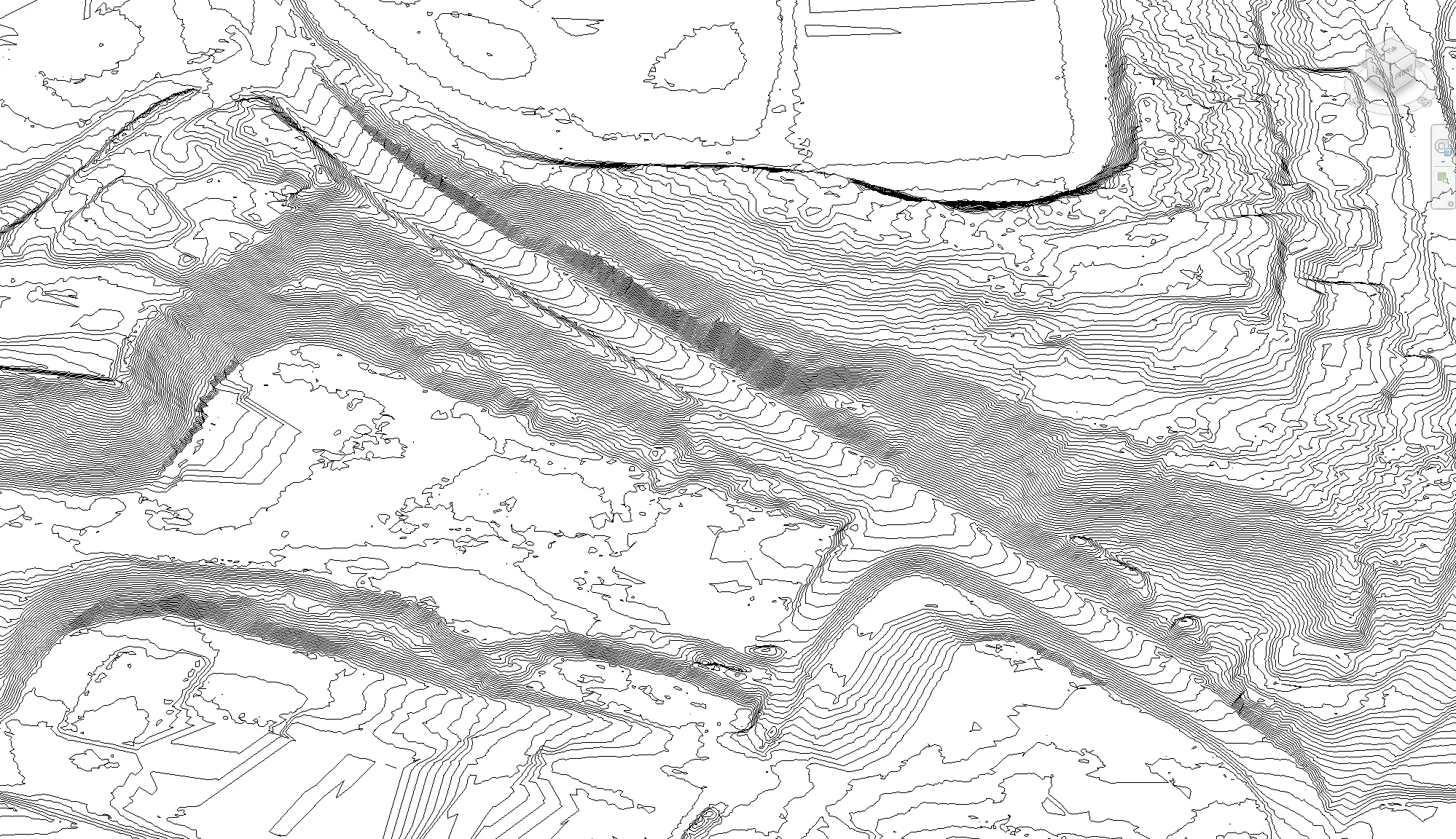
Revit terrain from Lidar points
The first conclusion is that the lidar terrain is way more detailed than the terrain created with contours. The landscape created with 1m contours is more abstract and less realistic.
The roads in the Lidar-generated model have an equal distance between the Revit contours, and it is possible to identify the edges of the road and the sidewalks. On the other hand, the terrain generated by the CAD model with contours creates an irregular slope for the road, with the curves being concentrated in a small zone instead of a natural slope. Revit does a lousy job of creating natural and realistic slopes with 1m curves due to a flawed interpolation algorithm. That we will see in more detail a bit ahead.
Flatter areas are also represented differently in the terrains generated with Lidar and CAD contours. In the Lidar terrain, we see more minor variations in the landscape based on the existence of points in that area that force Revit to create variation, while with the 1m CAD contours, that detail is not existing.
What is the deviation between toposurfaces generated with Lidar and 1m contours?
The road profile under it is generated by combining a section from the Lidar terrain (blue line) and a section from the the 1m contours terrain (red line). One can imediately see that the Lidar road profile (in blue) shows the correct slope of the road. It is also evident that these two lines (blue and red) meet at the points indicated with M. These M points are in fact the locations where the contours are located, so the levels match perfectly. However whan happens between the M points is a significant deviation.
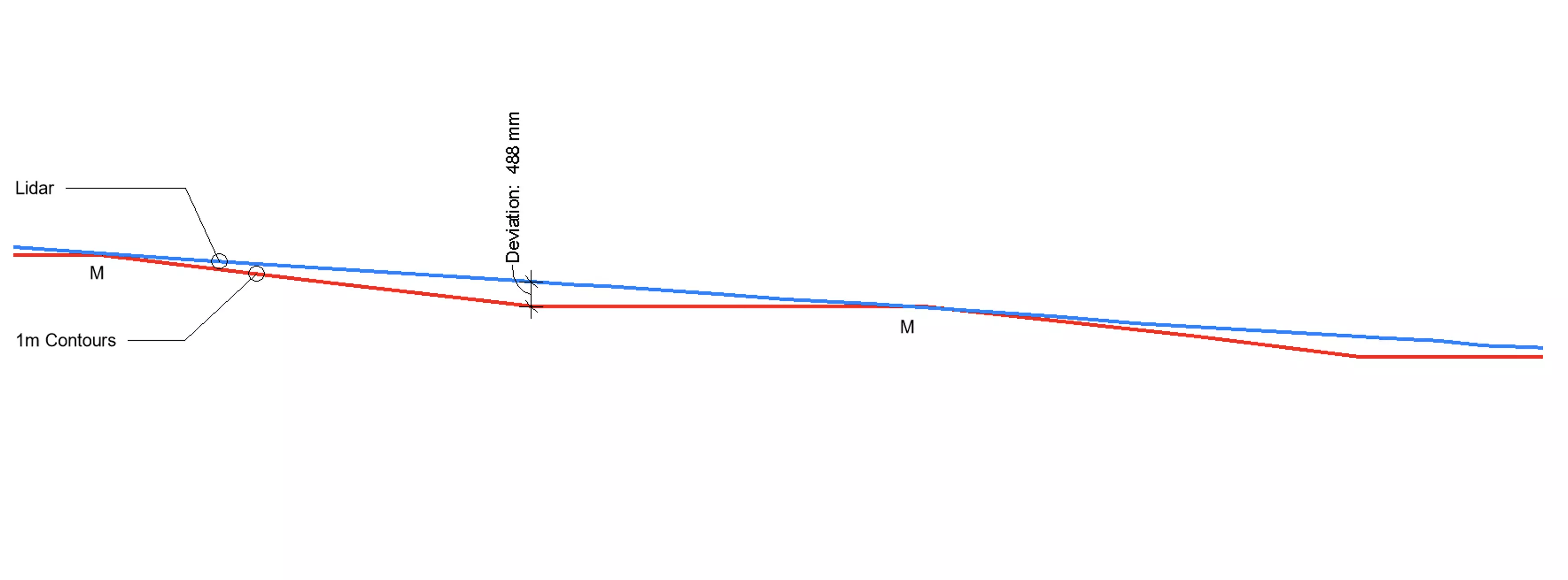
At half distance between the contours, Revit generated a terrain that is 488mm lower than the terrain generated from Lidar. This significant deviation is practice tells us two things. The terrain generated from Revit using the contours has a flaw in terms of interpolation and gives a wrong indication of the slope of the terrain, what can create errors in placing new structures. But in addition, the terrain that is generated from the contours also has an expressive lower volume than the terrain generated with Lidar, giving possibility for wrong terrain estimations.
Verdict
Using the latest method of topographic surveying created opportunities to generate more reliable terrain models in Revit. With archi topography one can import Lidar point clouds directly from the surveyor or national database of Lidar scans. More accuracy and precision in the digital terrain translates into better projects in terms of both positioning the structures correctly and cost estimations related with the terrain.

